
SYSTEM
100 cm
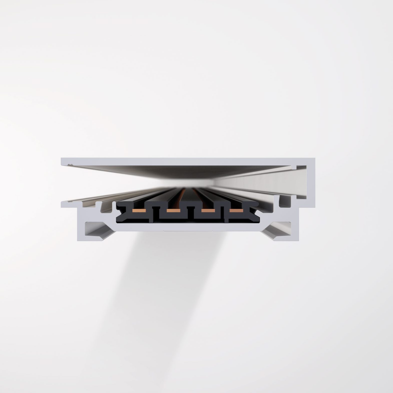
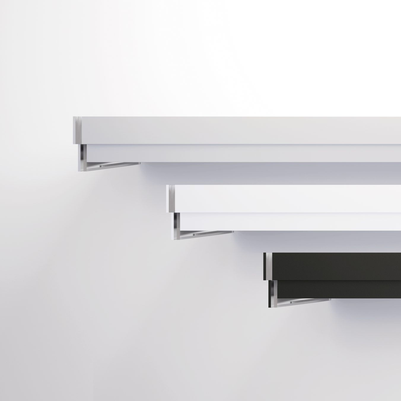
11010 Silver
11310 White
11510 Black
200 cm
11020 Silver
11320 White
11520 Black
300 cm
11030 Silver
11330 White
11530 Black
3 phase track
100 cm
14010 Silver
14310 White
14510 Black
200 cm
14020 Silver
14320 White
14520 Black
300 cm
14030 Silver
14330 White
14530 Black
3 phase track
100 cm
10010 Silver
10310 White
10510 Black
200 cm
10020 Silver
10320 White
10520 Black
300 cm
10030 Silver
10330 White
10530 Black
Cable management system
100 cm
70010 Silver
70310 White
70510 Black
200 cm
70020 Silver
70320 White
70520 Black
300 cm
70030 Silver
70330 White
70530 Black
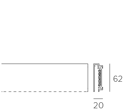
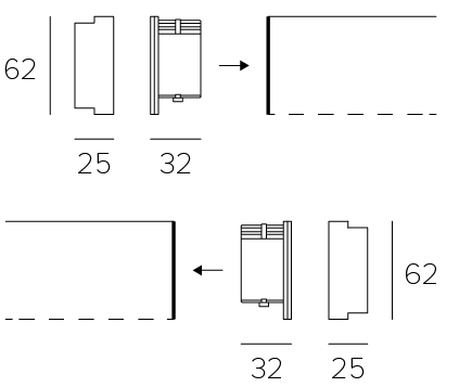
The dashed line indicates the open side of the track.
The dashed line indicates the open side of the track.
The dashed line indicates the open side of the track.
The dashed line indicates the open side of the track.
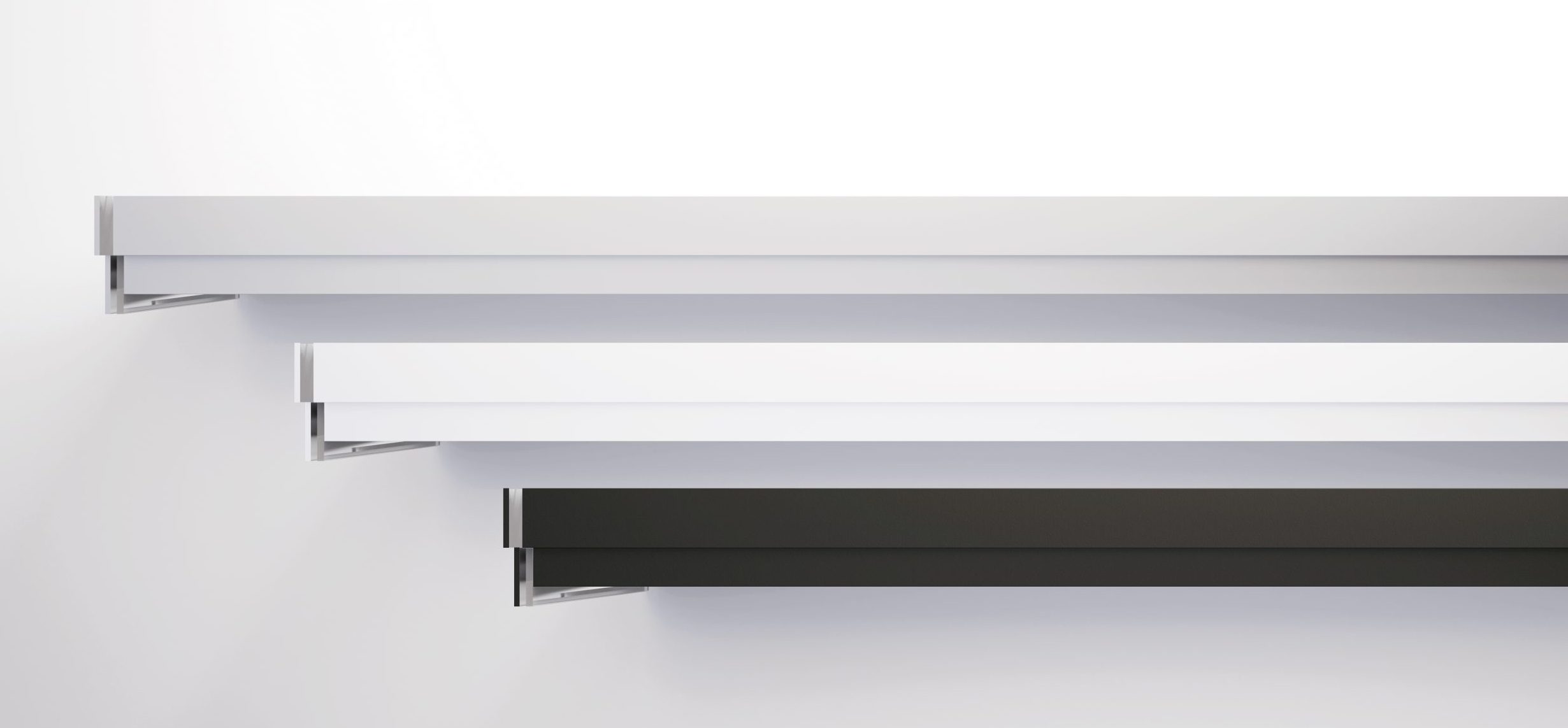
Extruded aluminium track, cut to size.
Extruded aluminium track, cut to size.
Extruded aluminium track, cut to size.
Extruded aluminium track, cut to size.
Kg 1 / 100cm
Kg 1 / 100cm
Kg 1 / 100cm
Kg 1 / 100cm
1 phase track
100 cm
11010 Silver
11310 White
11510 Black
200 cm
11020 Silver
11320 White
11520 Black
300 cm
11030 Silver
11330 White
11530 Black
The dashed line indicates the open side of the track.
Extruded aluminium track, cut to size.
Download
Kg 1 / 100cm
3 phase track
100 cm
14010 Silver
14310 White
14510 Black
200 cm
14020 Silver
14320 White
14520 Black
300 cm
14030 Silver
14330 White
14530 Black
The dashed line indicates the open side of the track.
Extruded aluminium track, cut to size.
Download
Kg 1 / 100cm
3 phase track
100 cm
10010 Silver
10310 White
10510 Black
200 cm
10020 Silver
10320 White
10520 Black
300 cm
10030 Silver
10330 White
10530 Black
The dashed line indicates the open side of the track.
Extruded aluminium track, cut to size.
Download
Kg 1 / 100cm
Cable management system
100 cm
70010 Silver
70310 White
70510 Black
200 cm
70020 Silver
70320 White
70520 Black
300 cm
70030 Silver
70330 White
70530 Black
The dashed line indicates the open side of the track.
Extruded aluminium track, cut to size.
Download
Kg 1 / 100cm
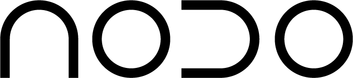
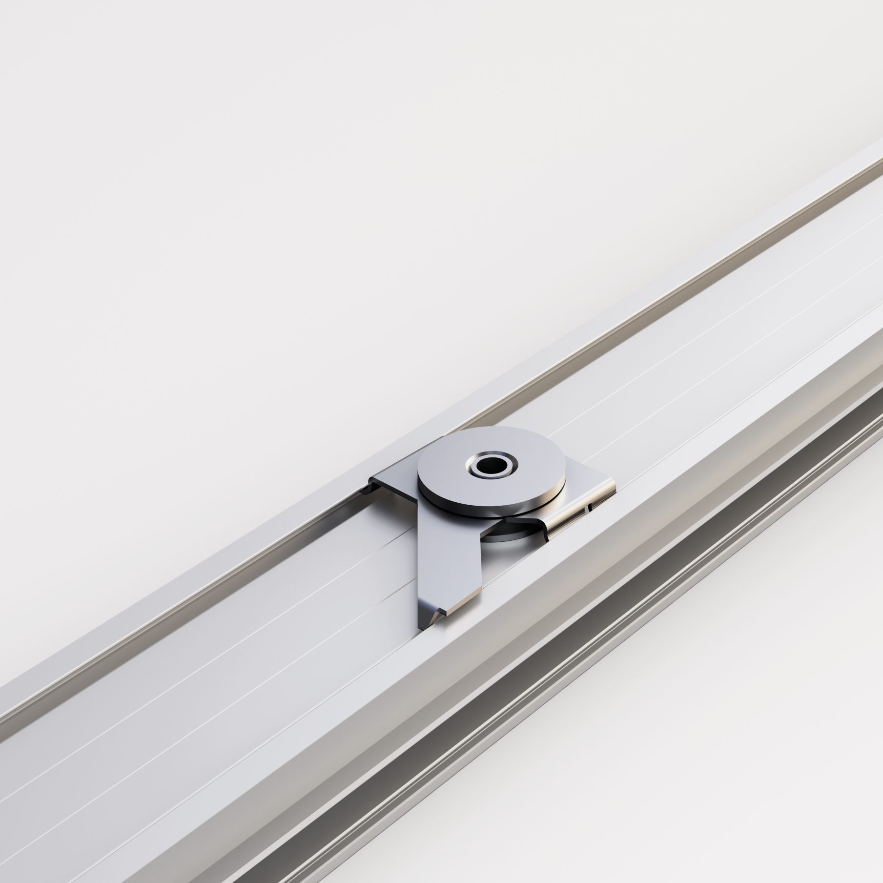
Track made of extruded aluminium size customizable.
Electrical copper conductors inserted in a profile of insulating material [glow wire 850°].
With a single-phase AC connection, the maximum load is 16A [3840W]. The 3-phase version of NODO track, if connected to 3-phase alternating current, allows a maximum load of 16A per phase [3 x 3840W = 11520 W].
The track has grooves that enable anti-glare installation of 8 mm LED strips on both sides [Side Light] and LED strip up to 20 mm on the back [Up Light] if suspended.
The track can be completed with supports, terminals, joints, power feeds and if necessary dust proof / steam seals. NODO allows elements to be powered at any point on the track.
It is possible to install the system to the ceiling, wall or fastened to the work surface. When the track is installed horizontally on the wall. the opened side must face down. Track can be cut to measure and must be installed by a qualified technician.
During installation, keep the minimum distances indicated with respect to possible encumbrances to allow the insertion of sockets, lights and accessories.
Made in compliance with lighting system and electrical conduit safety standards [CEI-EN 61534-1/21 and CEI-EN60598-1] to be installed in accordance with the installation provisions.
Nodo is protected internationally by industrial invention patents.
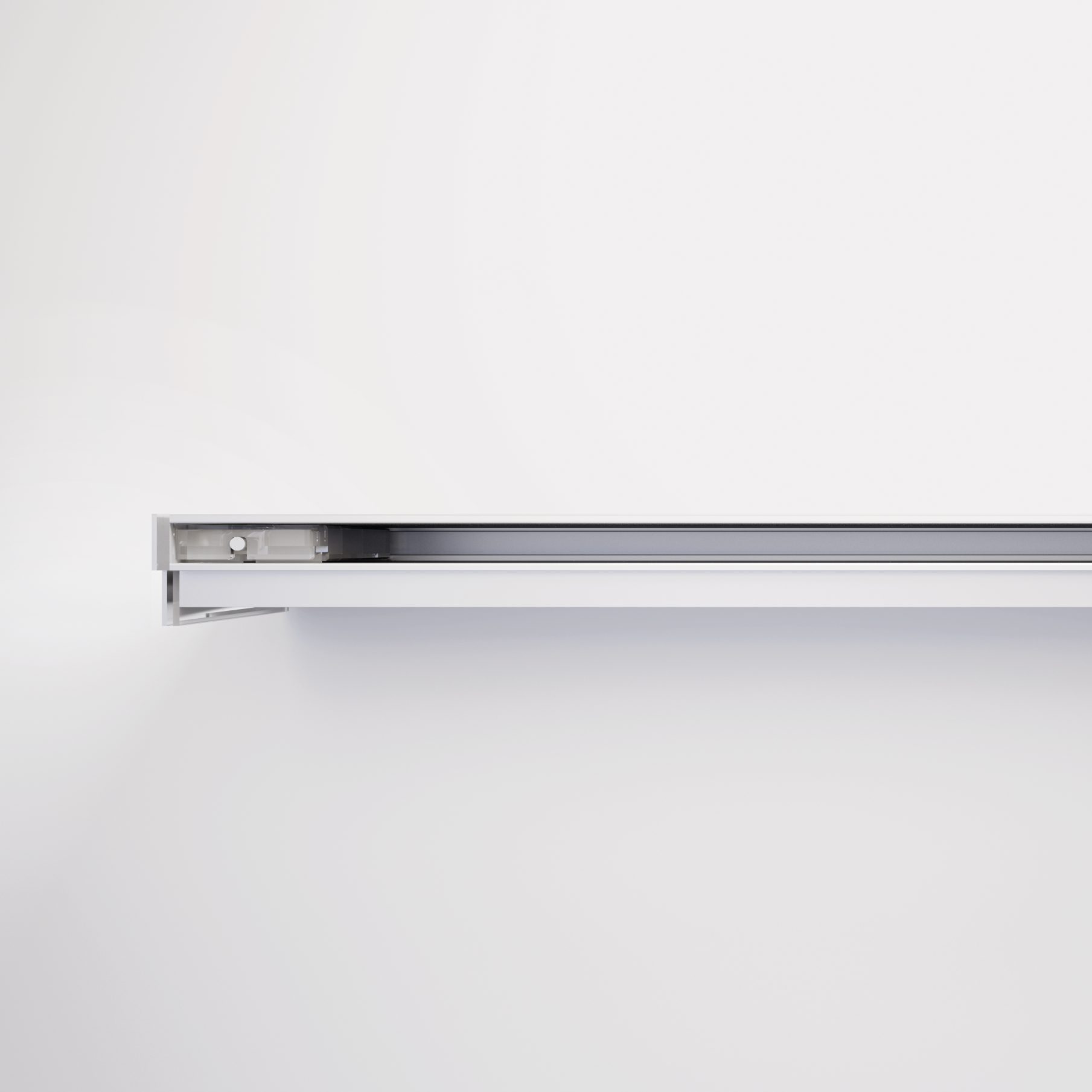
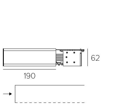
Power feed
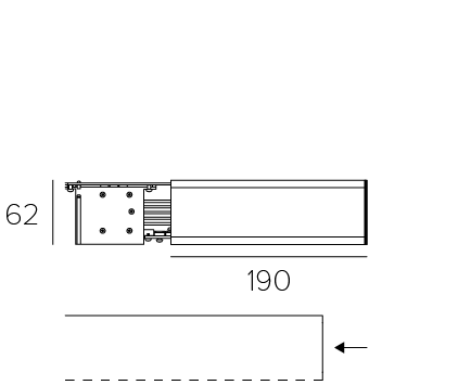
Power feed
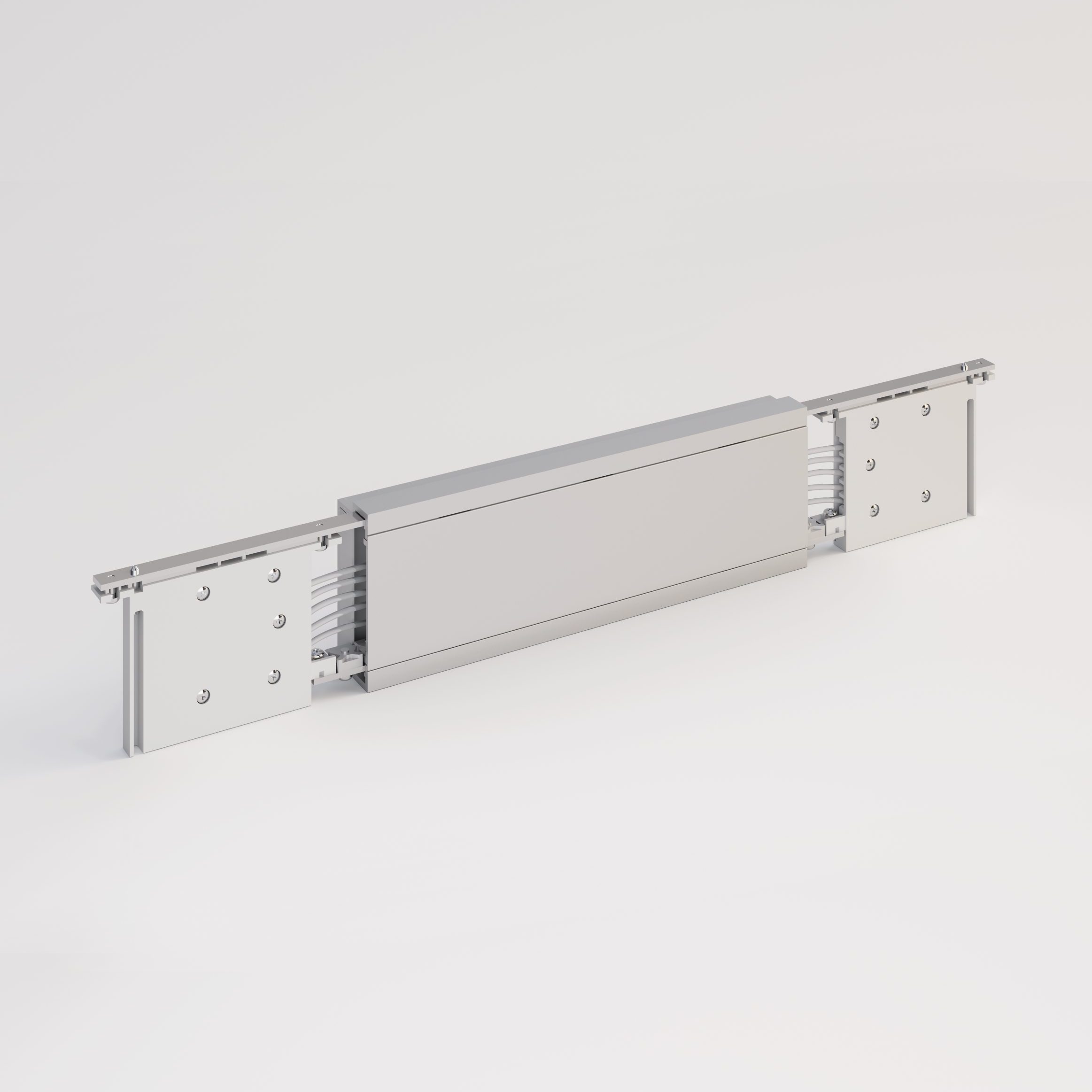
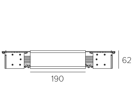
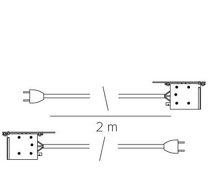
Central power feed
Plug wiring
Left
19056 White
19060 Black
Right
19000 Silver
19300 White
19500 Black
Central
19004 Silver
19304 White
19504 Black
Left
19056 White
19060 Black
Right
19054 White
19058 Black
Left
Right
Left
Right
The dashed line indicates the open side of the track.
The dashed line indicates the open side of the track.
Terminal
Terminal
Central power feed in aluminum.
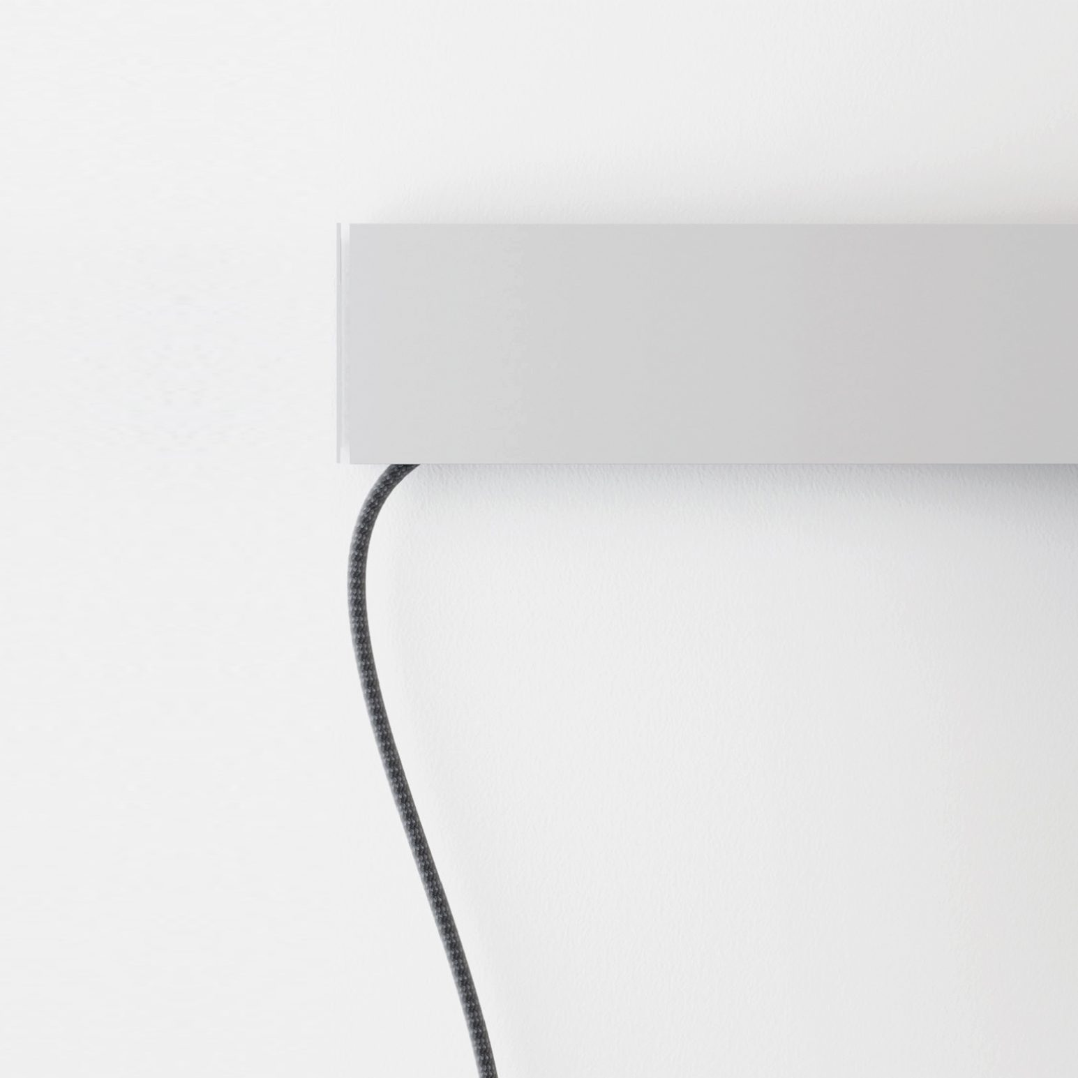
Power feed with wiring [3 x 1.5 mm2] covered in anthracite grey fabric.
Standard German plug.
Kg 0.38
Kg 0.38
Kg 0.44
Kg 0.15
Power feed
Left
19056 White
19060 Black
Left
The dashed line indicates the open side of the track.
Terminal
Download
Kg 0.38
Power feed
Right
19000 Silver
19300 White
19500 Black
Right
The dashed line indicates the open side of the track.
Terminal
Download
Kg 0.38
Central power feed
Central
19004 Silver
19304 White
19504 Black
Central power feed in aluminum.
Download
Kg 0.44
Plug wiring
Left
19056 White
19060 Black
Right
19054 White
19058 Black
Left
Right
Power feed with wiring [3 x 1.5 mm2] covered in anthracite grey fabric.
Standard German plug.
Download
Kg 0.15
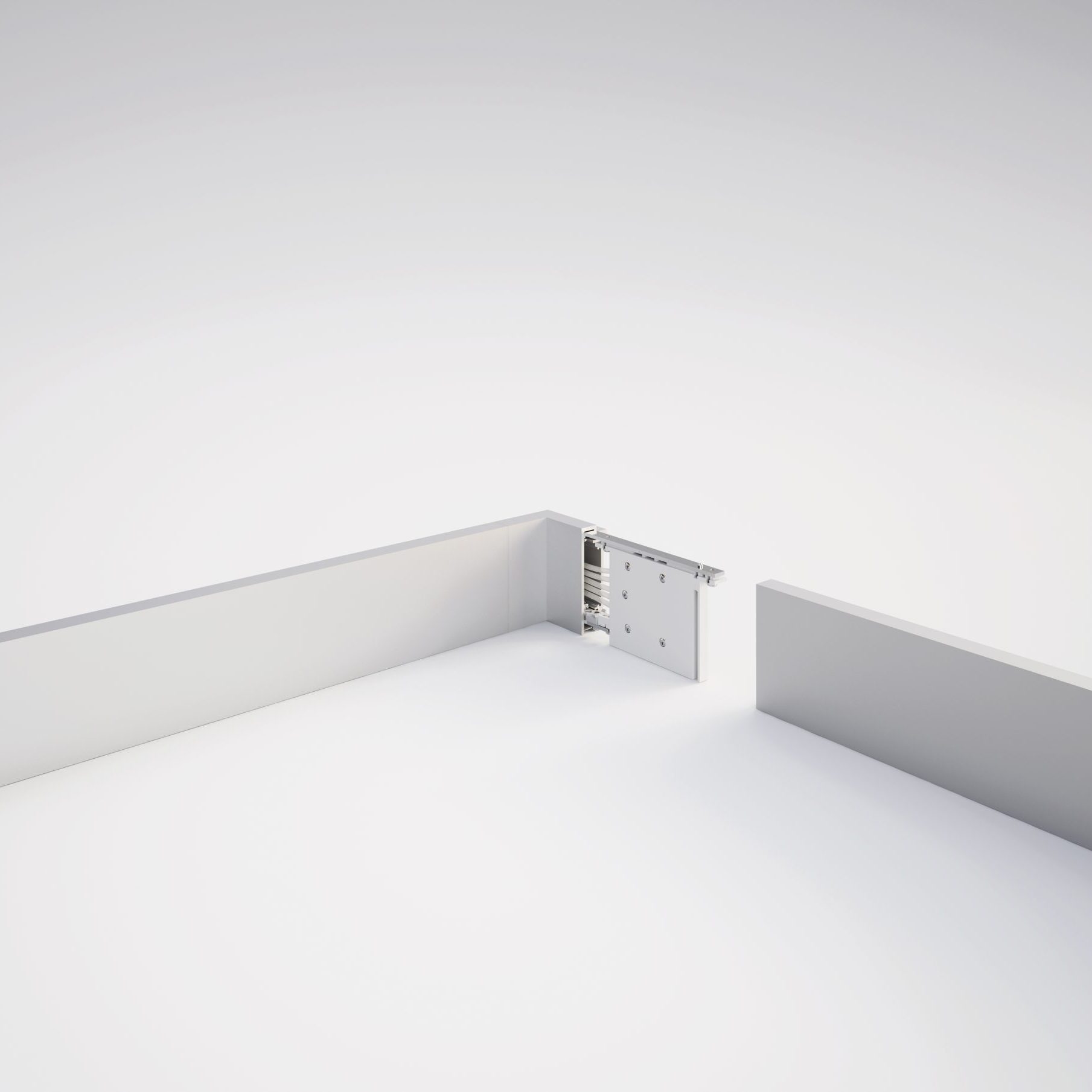
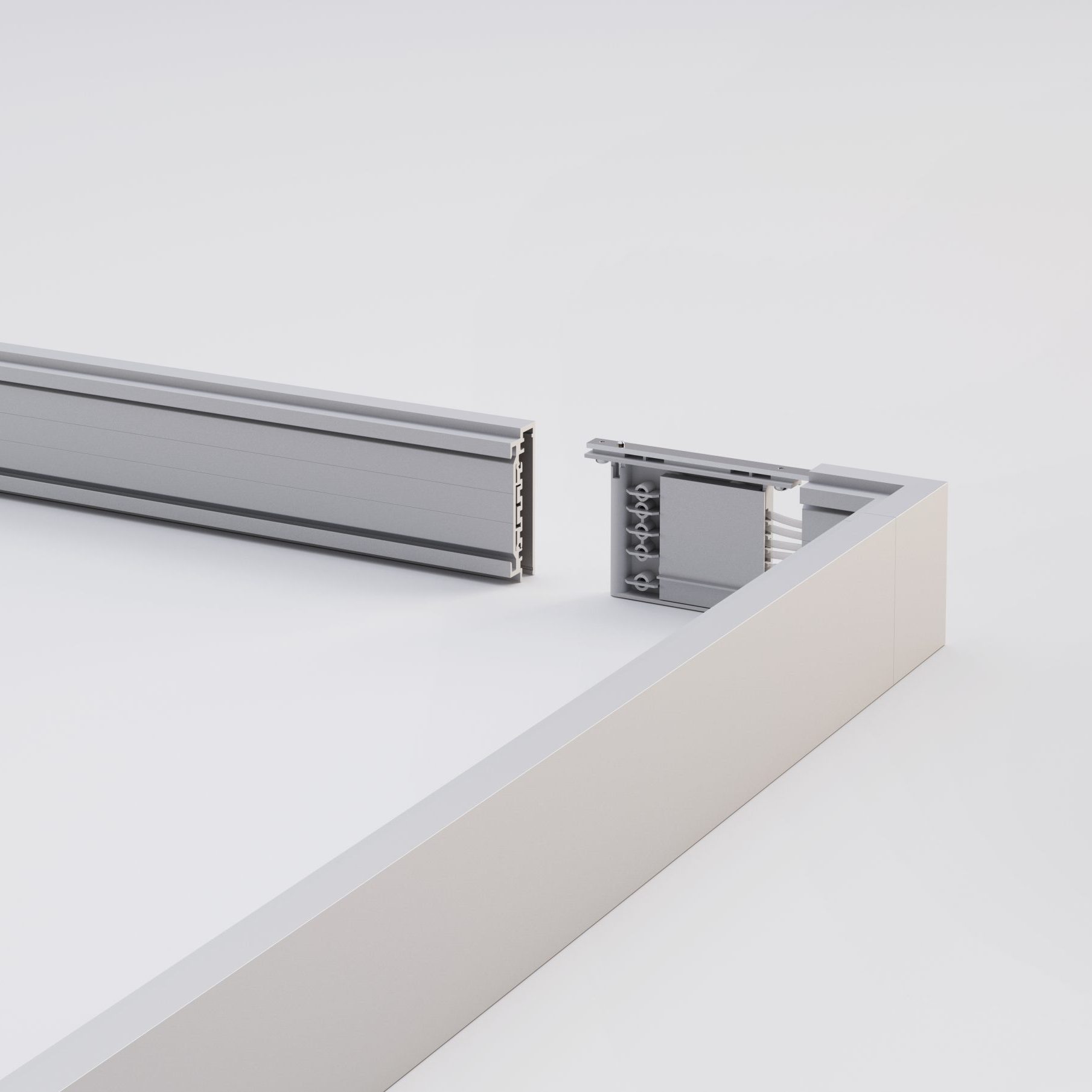
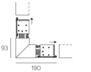
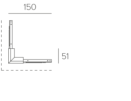
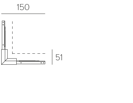
90° joint
90° joint
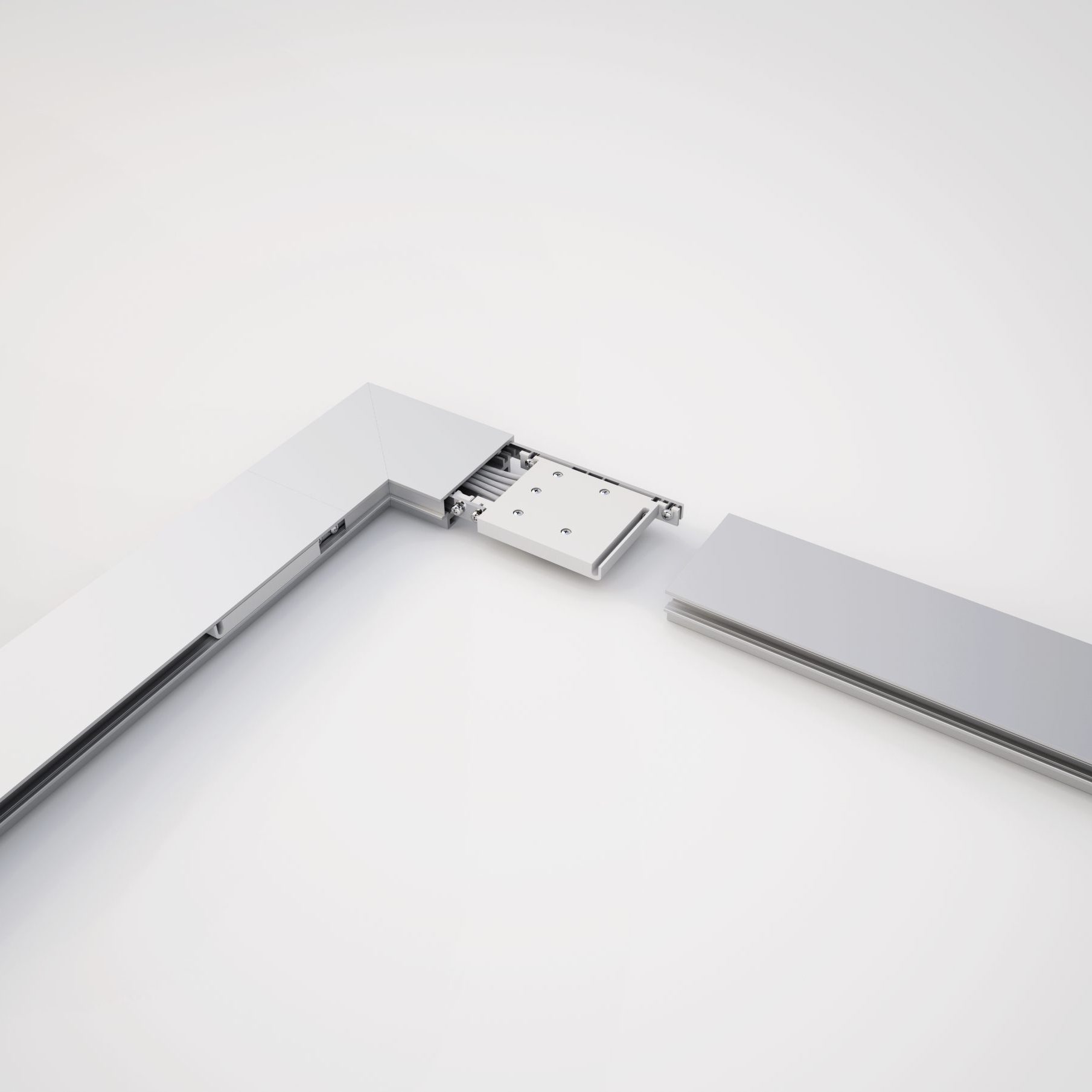
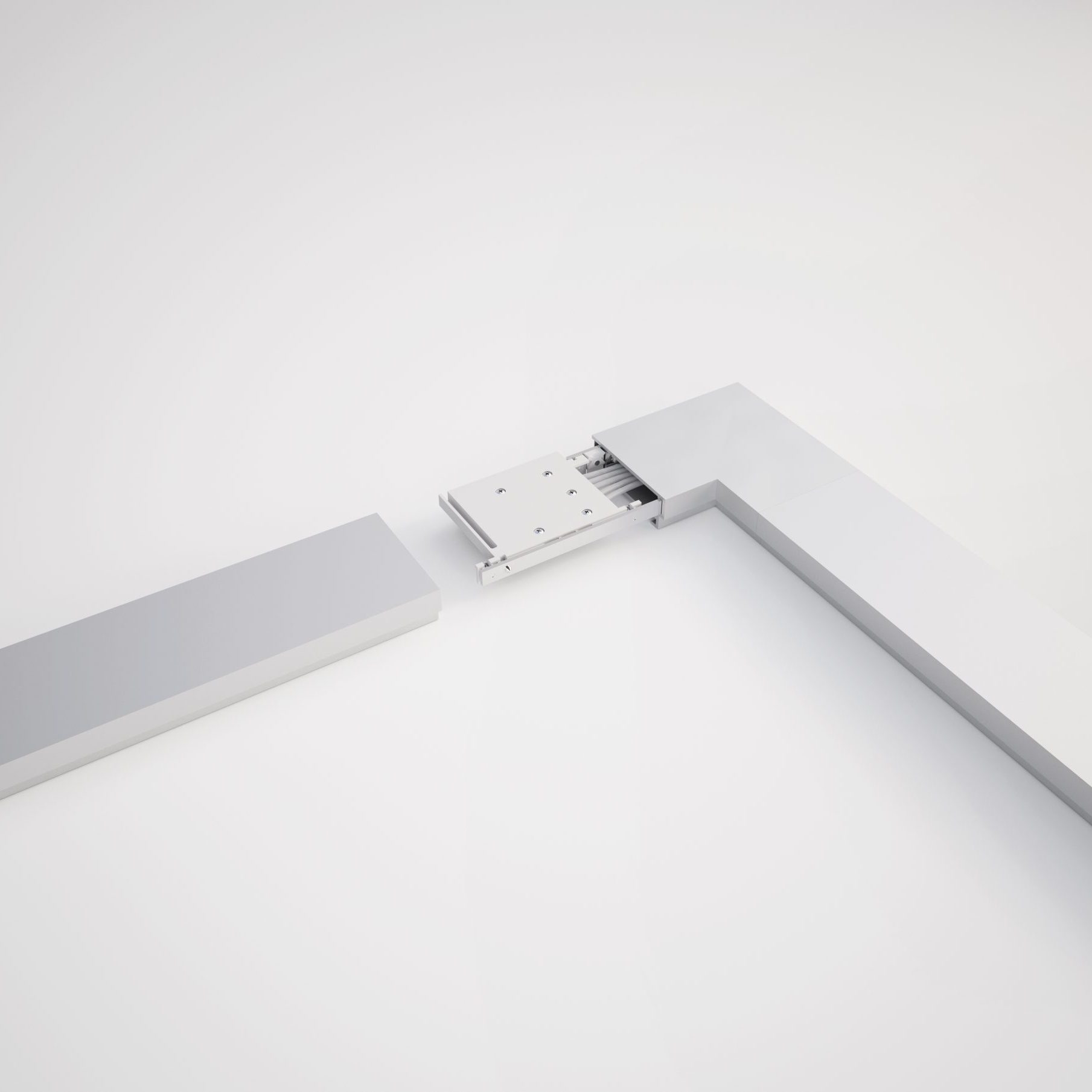
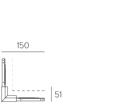
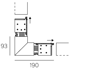
Angular joint
Angular joint
Internal
19006 Silver
19306 White
19506 Black
External
19008 Silver
19308 White
19508 Black
Internal
19016 Silver
19316 White
19516 Black
External
19018 Silver
19318 White
19518 Black
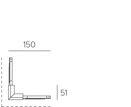
The dashed line indicates the open side of the track.
The dashed line indicates the open side of the track.
The dashed line indicates the wall.
The dashed line indicates the wall.
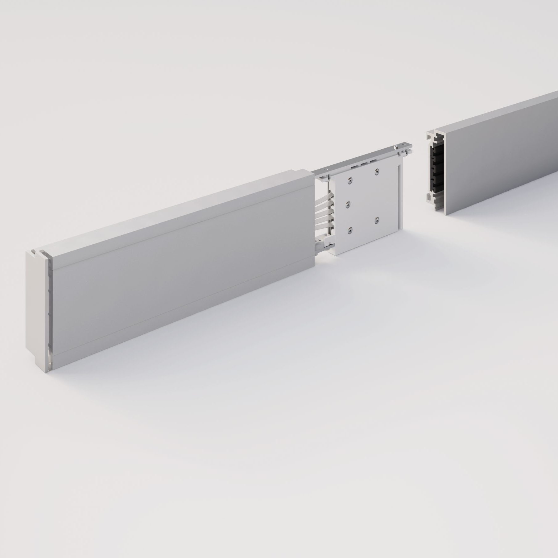
Enables the mechanical and electrical connection between two tracks.
Enables the mechanical and electrical connection between two tracks.
Enables the mechanical and electrical connection between two tracks.
Enables the mechanical and electrical connection between two tracks.
Kg 0.26
Kg 0.26
Kg 0.22
Kg 0.22
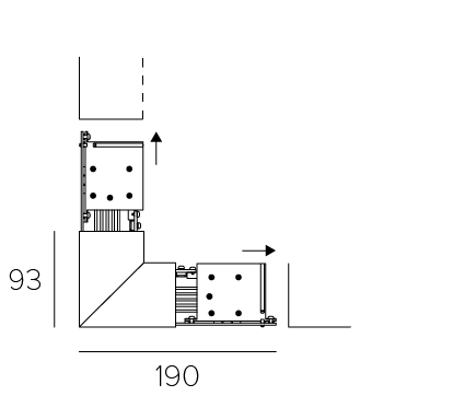
90° joint
Internal
19006 Silver
19306 White
19506 Black
The dashed line indicates the open side of the track.
Enables the mechanical and electrical connection between two tracks.
Download
Kg 0.26
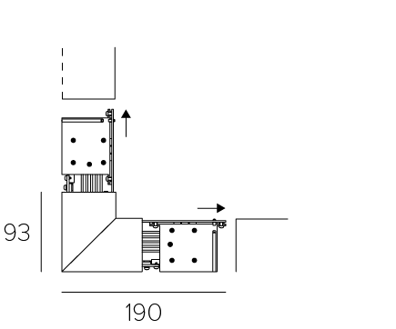
90° joint
External
19008 Silver
19308 White
19508 Black
The dashed line indicates the open side of the track.
Enables the mechanical and electrical connection between two tracks.
Download
Kg 0.26
Angular joint
Internal
19016 Silver
19316 White
19516 Black
The dashed line indicates the wall.
Enables the mechanical and electrical connection between two tracks.
Download
Kg 0.22
Adjustable joint
External
19018 Silver
19318 White
19518 Black
The dashed line indicates the wall.
Enables the mechanical and electrical connection between two tracks.
Download
Kg 0.22
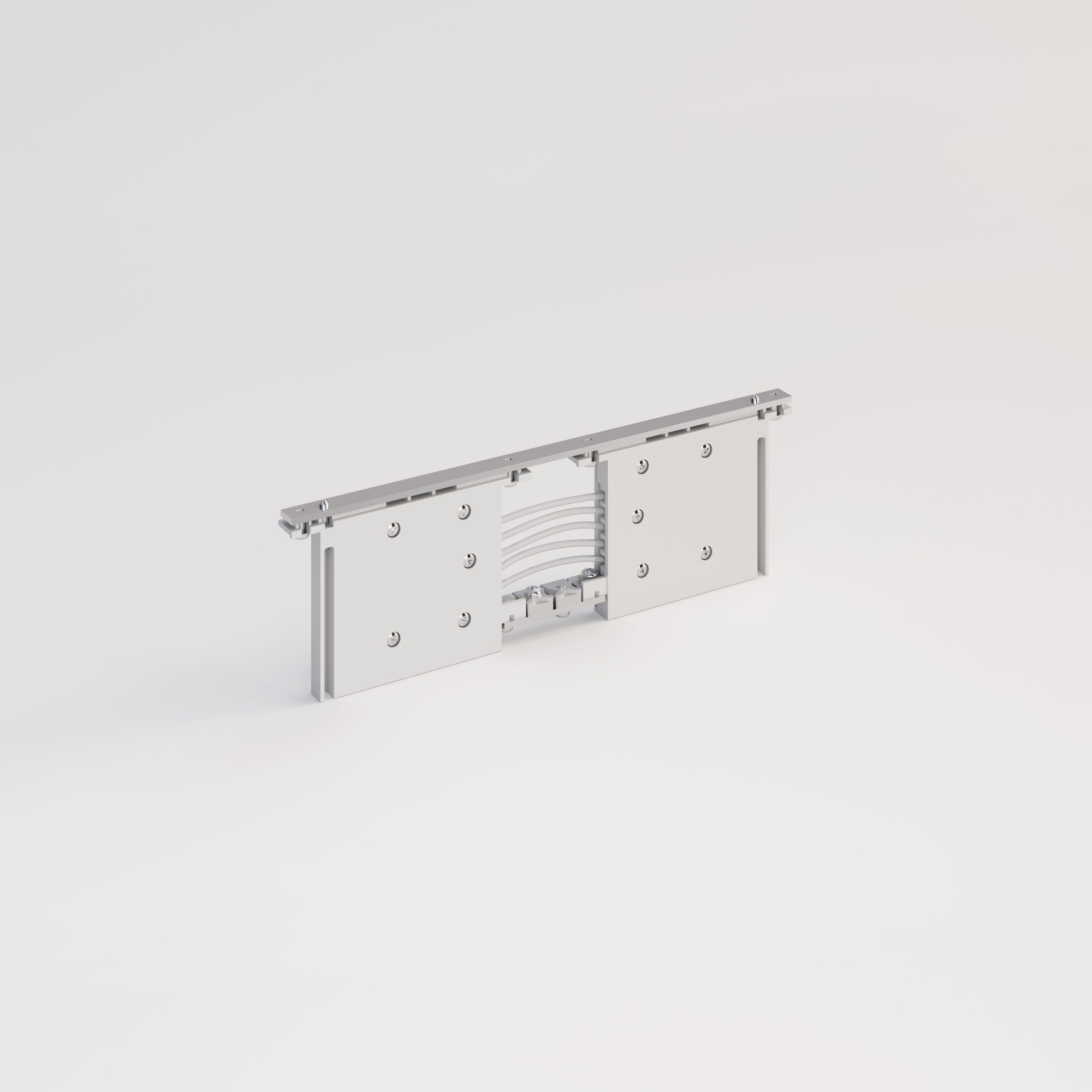
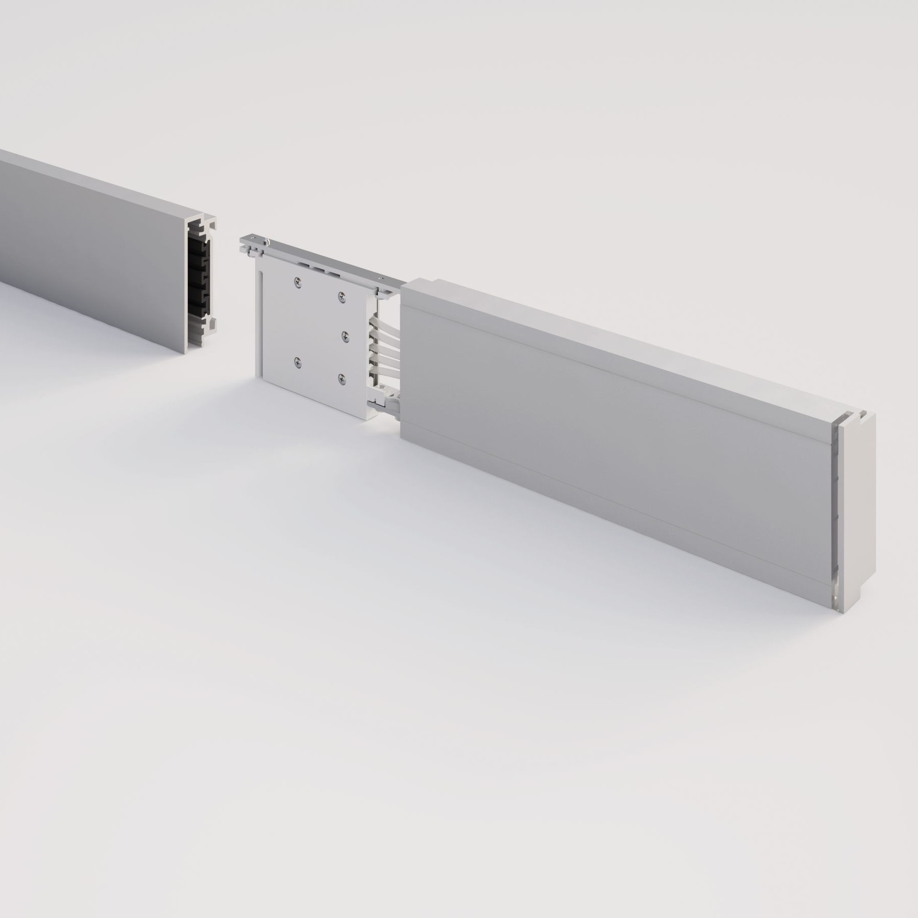
Linear coupling
Direct wall/ceiling support
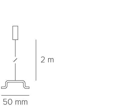
Suspension ceiling support
Terminal
Conductor
19066 White
19068 Black
19026 Direct support
19030 200cm wire support
Strain relief kit
19040 Kit
It must be combined with the power supplies when the track is suspended.
Left
19037 Silver
19337 White
19537 Black
Right
19035 Silver
19335 White
19535 Black
It is housed between the two tracks.
The dashed line indicates the wall.
The Conductive Joint allows the mechanical connection and the electrical connection between two tracks.
The insulating joint allows the mechanical connection between two tracks allowing electrical separation between the sectors, each of which must be powered.
The use of a support every 100 cm of the track allows for a maximum load of 10 Kg per meter.
Install the ceiling/wall mounting devices, in correspondence with the end parts of the installation and near the joints.
The use of a support every 100 cm of the track allows for a maximum load of 10 Kg per meter.
Install the ceiling support near the terminal parts of the installation and near the joints. Plate with holes for track balance..
Made of insulating plastic material with anodized aluminium cover.
Kg 0.12
Kg 0.05
Kg 0.08
Kg 0.02
Linear coupling
Conductor
19066 White
19068 Black
It is housed between the two tracks.
The Conductive Joint allows the mechanical connection and the electrical connection between two tracks.
The insulating joint allows the mechanical connection between two tracks allowing electrical separation between the sectors, each of which must be powered.
Download
Kg 0.12
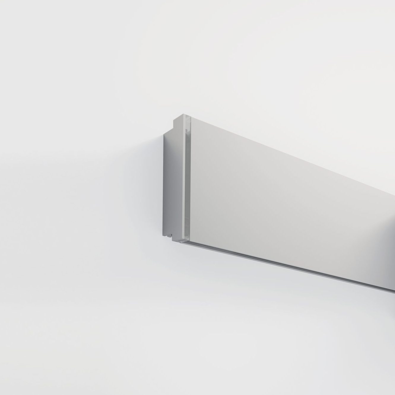
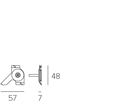
Direct wall/ceiling support
19026 Direct support
The use of a support every 100 cm of the track allows for a maximum load of 10 Kg per meter.
Install the ceiling/wall mounting devices, in correspondence with the end parts of the installation and near the joints.
Download
Kg 0.05
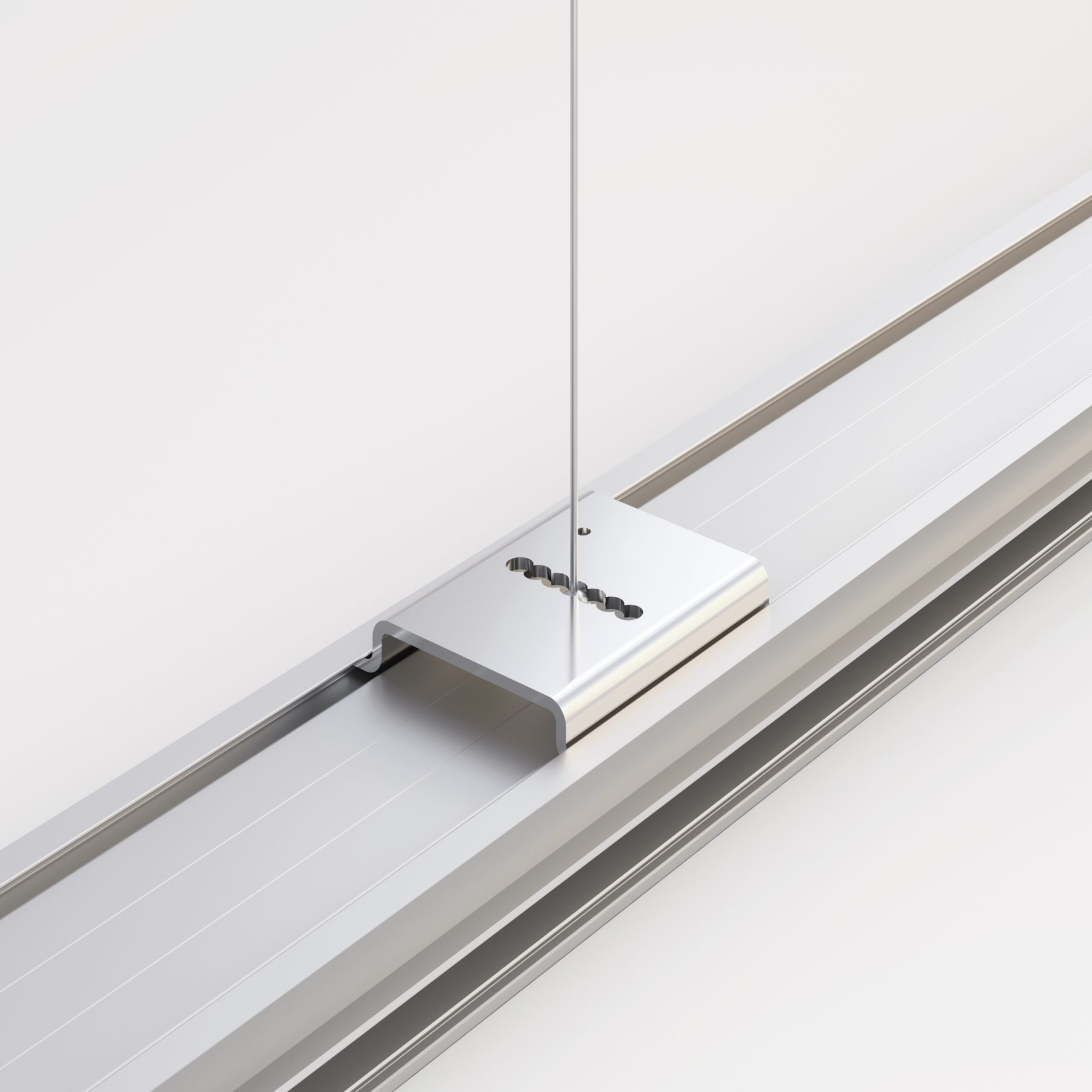
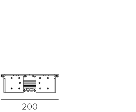
Suspension ceiling support
19030 200cm wire support
Strain relief kit
19040 Kit
It must be combined with the power supplies when the track is suspended.
The use of a support every 100 cm of the track allows for a maximum load of 10 Kg per meter.
Install the ceiling support near the terminal parts of the installation and near the joints. Plate with holes for track balance..
Download
Kg 0.08
Terminal
Left
19037 Silver
19337 White
19537 Black
Right
19035 Silver
19335 White
19535 Black
The dashed line indicates the wall.
Made of insulating plastic material with anodized aluminium cover.
Download
Kg 0.02